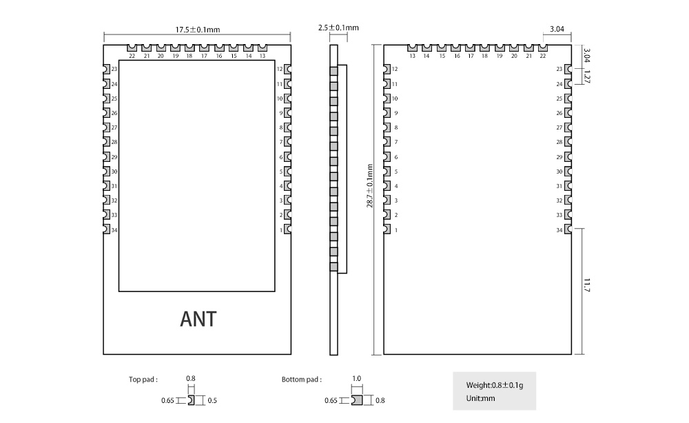
| pin number | pin name | Pin
Orientation | pin usage
|
| 1 | GND | - | Ground wire, connected to the power reference ground |
| 2 | DIO_7 | output
| STATUS_LED , status indicator, active low. Long light is in standby
state, fast blinking means creating a new network or joining a network, 1S periodic blinking means allowing network access; |
| 3 | DIO_8 | -
| NC pin, floating; |
| 4 | DIO_9 | -
| NC pin, floating; |
| 5 | DIO_10 | -
| NC pin, floating; |
| 6 | DIO_11 | -
| NC pin, floating; |
| 7 | DIO_12 | input
| UART_RX , serial port input signal pin; |
| 8 | DIO_13 | output
| UART_TX , serial port output signal pin; |
| 9 | DIO_14
| -
| dangling; |
| 10 | DIO_15
| input
| BOOT_LOADER , active low; |
| 11、12 | GND
| -
| Ground wire, connected to the power reference ground; |
| 13 | JTAG_TMSC
| input /
output
| JTAG_TMSC , if not used, please leave it empty; |
| 14 | JTAG_TCKC | input /
output
| JTAG_TMSC , if not used, please leave it empty; |
| 15 | DIO_16
| input /
output
| JTAG_TDO , if not used, please leave it empty; |
| 16 | DIO_17
| input /
output
| JTAG_TDI , if not used, please leave it empty; |
| 17 | DIO_18
| -
| NC pin, floating;
|
| 18 | DIO_19
| -
| NC pin, floating; |
| 19 | GND | - | Ground wire, connected to the power reference ground |
| 20 | VCC | - | The module power supply is positive reference power, the voltage range is 1.9 ~ 3.8V ; |
| 21 | DIO_20 | -
| NC pin, floating; |
| 22 | DIO_21 | -
| NC pin, floating; |
| 23 | GND | -
| Ground wire, connected to the power reference ground; |
| 24 | RESET_N | enter | Reset pin, active low; |
| 25 | DIO_22
| -
| NC pin, floating; |
| 26 | DIO_23 | - | NC pin, floating; |
| 27 | DIO_24
| -
| NC pin, floating; |
| 28 | DIO_25 | - | NC pin, floating; |
| 39 | DIO_26
| -
| NC pin, floating; |
| 30 | DIO_27
| -
| NC pin, floating; |
| 31 | DIO_28 | - | NC pin, floating; |
| 32 | DIO_29
| -
| NC pin, floating; |
| 33 | DIO_30 | -
| NC pin, floating; |
| 34 | GND | -
| Ground wire, connected to the power reference ground;
|


