SX1278

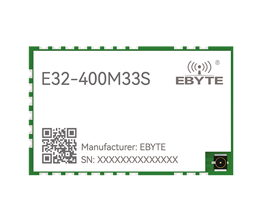
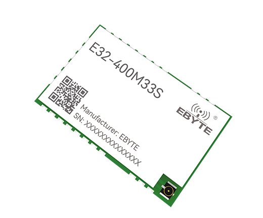
E32-400M33S SX1278 чип Lora модуль-аппаратный модуль SPI-модуль расширения спектра Ebyte LORA


[Чип-решение]: SX1278
[Мощность передачи]: 33 дБм
[Расстояние связи]: 16 км
[Размер продукта]: 24*38,5 мм
[Введение]: E32-400M33S — это беспроводной модуль LoRaTM патч-типа с частотой 410–493 МГц и максимальной мощностью передачи 2 Вт, независимо разработанный на основе SX1278, производимый Semtech в США. Поскольку в качестве ядра модуля используется импортный SX1278, на оригинальной основе встроены усилитель мощности (УМ) и малошумящий усилитель (МШУ), благодаря чему максимальная мощность передачи достигает 1 Вт, а чувствительность приема еще больше. улучшена общая связь стабильна. Производительность значительно улучшена по сравнению с продуктами без усилителя мощности и малошумящего усилителя. Этот модуль в основном предназначен для умных домов, считывания показаний беспроводных счетчиков, научных исследований и медицинского обслуживания, а также оборудования беспроводной связи на средние и большие расстояния.

图片关键词

图片关键词

图片关键词

图片关键词

图片关键词

图片关键词

图片关键词

图片关键词

Main parametersperformanceRemark
minimum valuemaximum value
Supply voltage (V)05.5Exceeding 5.5V will permanently burn the module
Blocking power (dBm)-10LNA may burn if used at close range
Working temperature (℃)-4085Industrial grade
Main parametersPerformanceRemark
Minimum valueTypical valueMaximum value
Working voltage (V)3.355.5>5.5V can cause permanent damage to the module;
Communication level (V)-3.3--
Working temperature (℃)-40-85Industrial grade design
Working frequency band (MHz)410-493-
Power consumptionEmission current (mA)-1100--
Receive current (mA)-19--
Sleep current (μA)-2--
Maximum transmit power (dBm)-33

Receiving sensitivity (dBm)-123-124-125The air rate is 1.2kbp
Main parametersdescribeRemark
reference distance16KmIn a clear and open environment, the antenna gain is 5dBi, the antenna height is 2 meters, and the air rate is 2.4kbps.
FIFO256ByteMaximum length of a single send
Crystal frequency32MHzPassive crystal oscillator
Modulation methodLoRa TM (recommend)FSK/GFSK/MSK/GMSK/OOK
Packaging methodSMD typeSpacing 2.54mm
Interface mode2.54mmstamp hole
Communication interfaceSPI0~10Mbps
Overall dimensions24*38.5mm-
Antenna interfaceStamp hole/IPEXEquivalent impedance is about 50Ω
weight5.5g-


图片关键词

serial numberpinPin directionRemark
1GND-Ground wire, connected to the power reference ground
2GND-Ground wire, connected to the power reference ground
3GND-Ground wire, connected to the power reference ground
4GND-Ground wire, connected to the power reference ground
5GND-Ground wire, connected to the power reference ground
6RXENinputThe radio frequency switch receives the control pin, connects to the external microcontroller IO, and is active at high level.
7TXENinputRF switch emission control pin, connected to external microcontroller IO, active at high level
8DIO2input/outputConfigurable general-purpose IO port (see SX1276 manual for details)
9VCC-Power supply, range 3.3~5.5V (it is recommended to add external ceramic filter capacitors)
10VCC-Power supply, range 3.3~5.5V (it is recommended to add external ceramic filter capacitors)
11GND-Ground wire, connected to the power reference ground
12GND-Ground wire, connected to the power reference ground
13NC-hanging in the air
14DIO3input/outputConfigurable general-purpose IO port (see SX1276 manual for details)
15DIO4input/outputConfigurable general-purpose IO port (see SX1276 manual for details)
16GOD5input/outputConfigurable general-purpose IO port (see SX1276 manual for details)
17GND-Ground wire, connected to the power reference ground
18GND-Ground wire, connected to the power reference ground
19DIO1input/outputConfigurable general-purpose IO port (see SX1276 manual for details)
20GOD0input/outputConfigurable general-purpose IO port (see SX1276 manual for details)
21NRSTinputChip reset trigger input pin
22MISOoutputSPI data output pin
23SMOKEinputSPI data input pin
24SCLKinputSPI clock input pin
25NSSinputModule chip select pin, used to start an SPI communication
26GND-Ground wire, connected to the power reference ground
27ON-Antenna interface, stamp hole (50Ω characteristic impedance)
28GND-Ground wire, connected to the power reference ground


Certification

图片关键词Руководство.pdf


关联内容