| 1 | M0 | Input (very weakpull-up) | Cooperate with M1 to determine the 4 working modes of the module (can not be suspended, if not used, it can be grounded) |
| 2 | M1 | Input (very weakpull-up) | Cooperate with M0 to determine the 4 working modes of the module (can not be suspended, if not used, it can be grounded) |
| 3 | RXD | enter | TTL serial port input, connected to the external TXD output pin; |
| 4 | TXD | output | TTL serial output, connected to external RXD input pin; |
| 5 | AUX | output | Used to indicate the working state of the module; the user wakes up the external MCU, and outputs a low level during the power-on self-test initialization; (can beleft floating) |
| 6 | VCC | enter | Module power positive reference, voltage range: 3.3 ~ 5.5V DC |
| 7 | GND | enter | Module ground |
| 8 | SWCLK | enter | The clock pin when the program is loaded (floating, the user does not need to connect) |
| 9 | GND | enter | The clock pin when the program is loaded (floating, the user does not need toconnect) |
| 10 | SWDIO | enter | The clock pin when the program is loaded (floating, the user does not need to connect) |
| 11 | +3.3V | enter | The clock pin when the program is loaded (floating, the user does not need to connect) |
| 12 | P24 | input/output | NC pin, this pin needs to be left floating (for subsequent expansion use 13 NC - NC pin, use floating |
| 14 | NC | - | NC pin, use floating |
| 15 | GND | - | Power ground, fixing hole |
| 16 | GND | - | Power ground, fixing hole |
| 17 | GND | - | Power ground, fixing hole |
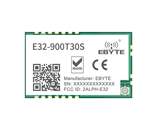
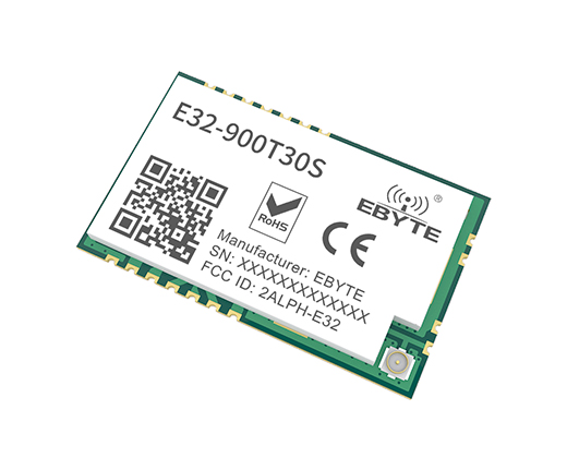
| 18 | AN | output | Antenna interface (high frequency signal output, 50Ω characteristic impedance) |